AEL Contempo 245
Lantern acquired in August 2021.
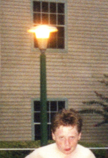
My first, and probably only, American lantern entered the Collection as a result of some idle eBay browsing (is there any other type?). I happened to spot a lantern for sale that I recognised, but couldn't recall why. A quick look back at some photographs taken during a family holiday to Florida in the late 1990s revealed a possible theory - the hotel complex where we stayed used lanterns bearing more than a passing resemblance to the type on sale. Most peculiarly, I didn't pay attention to street lighting at the time of the holiday (shock, horror!), but clearly, something was memorised that was rekindled at the sight of this listing. Needless to say, the item was bought, despite a rather high cost, owing to the postage and import charges, and arrived only a couple of weeks later, having travelled through multiple time zones in the process! The AEL abbreviation stands for American Electric Lighting, in case you were wondering.
The picture that inspired the purchase, complete with me looking especially psychotic, for some reason.
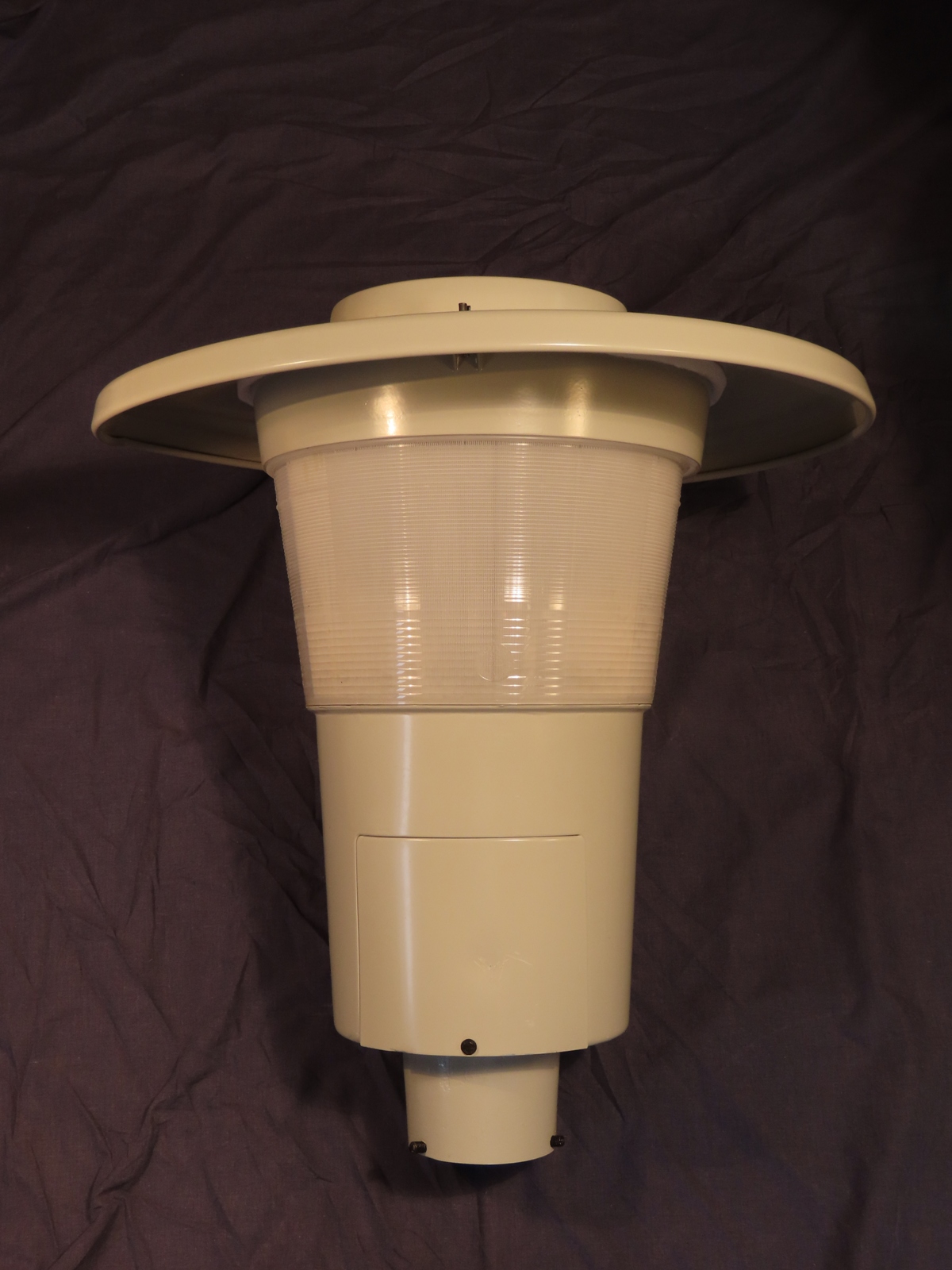
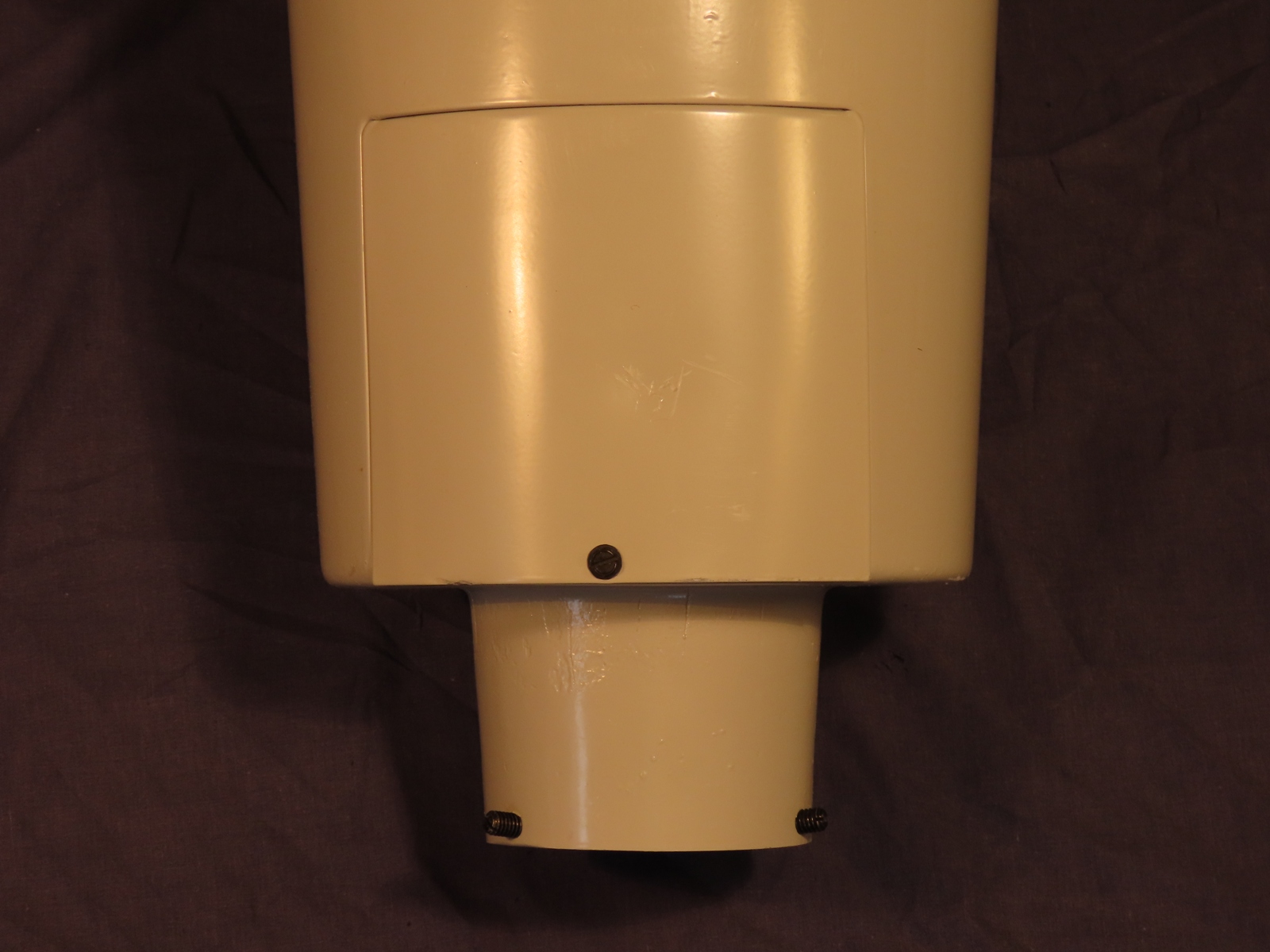
Although the base of the acquired lantern appears less tapered than that on the installed example was, it's a very close match (I believe that both GE and Cooper Lighting produced similar designs). The lantern measures 22 inches (559 mm) in width and 24.5 inches (622 mm) in height, and the base section accommodates a spigot of 3.2 inches (81 mm) in length. The long base casting reminds me of early gear-in-head versions of the SOX Thorn Gamma 6; the long base being a necessity, owing to the size of the leak transformer. The same is true for this lantern, with a chunky 250 Watt ballast being housed in the base (the pictured example above is likely to be running a much lower wattage lamp, however). A removable panel within this casting allows access to the supply cable connector.
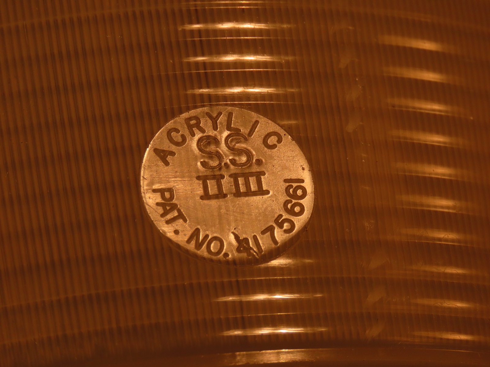
The prismatic refractor bowl is acrylic, as confirmed by this moulded detail on the 'front' of the lantern.
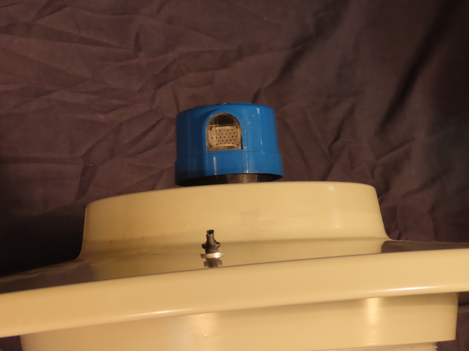
The wide-brimmed canopy hinges onto the top section of the lantern, and is secured with a single wing nut that threads through a fixed aperture.
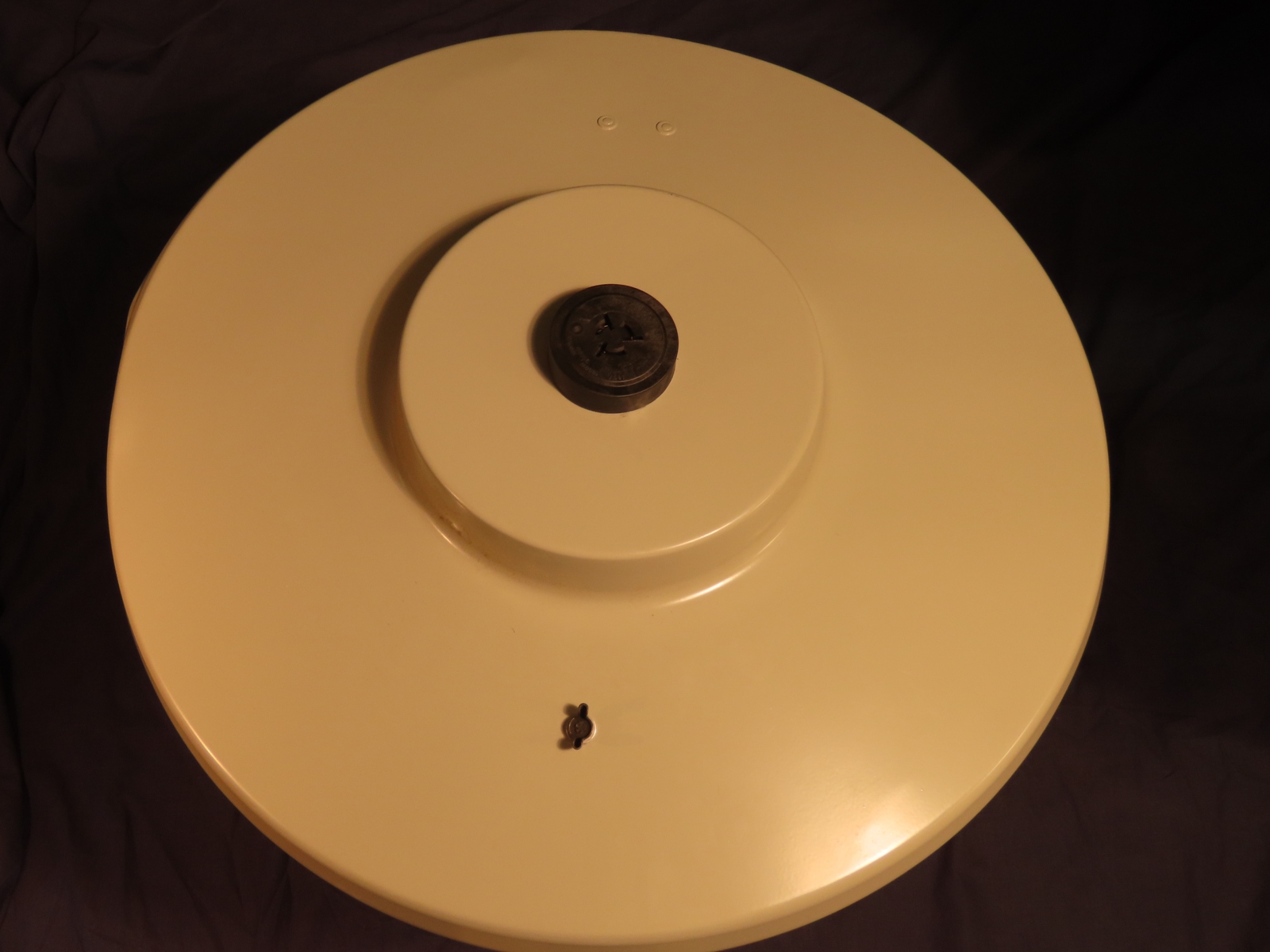
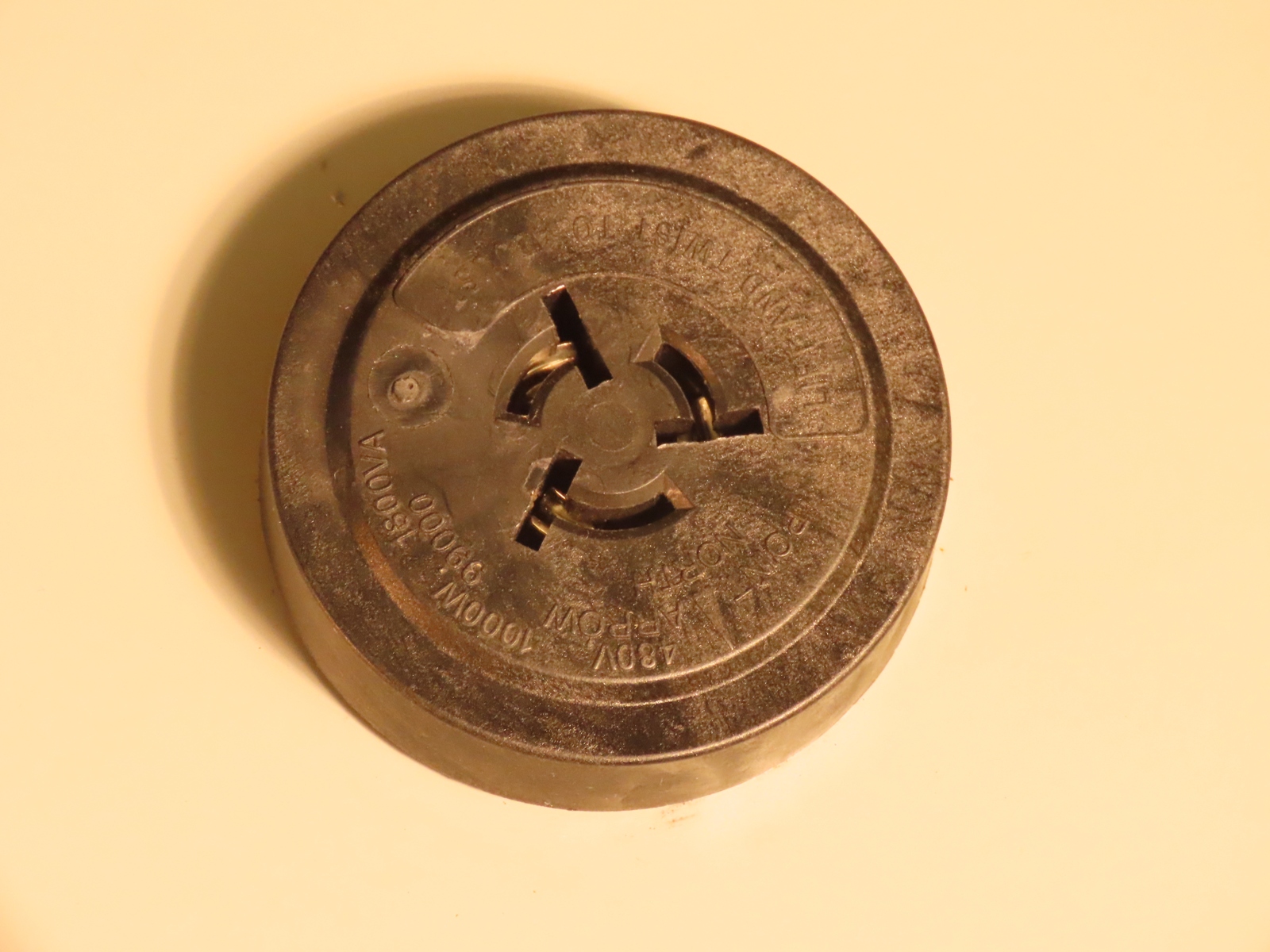
A three-pin NEMA socket is fitted in the centre of the canopy. Although British photocells will go into the slots, turning them to lock is difficult, not least because, unlike NEMA sockets on British lanterns, which are fixed in place, this NEMA socket can be lifted and rotated, in order that it is aligned correctly for correct switching - American photocells tend to have the detector located on the side of the unit, and this must face north, whereas British photocells have the detector pointing upwards, negating the need for the socket to be positioned at the correct alignment.
The American-style Longjoin JL-201C photocell fits the NEMA socket correctly; this image demonstrates how it looks on the canopy.
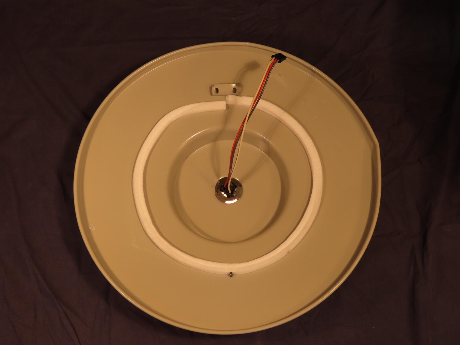
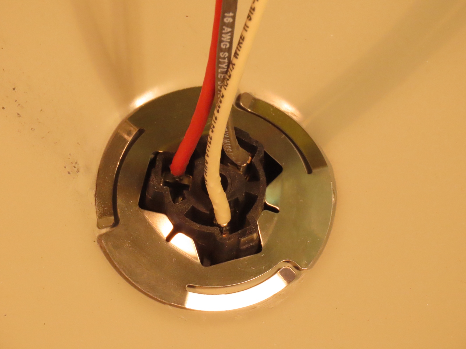
The three wires that connect the NEMA socket terminate in a connector, allowing the canopy to be removed completely without having to disconnect any wires using tools. Of course, the lantern is wired in the American colours (definitely not "colors"!) of black for Phase (i.e. "live") and white for Neutral. The Load conductor here is identified as red. A rather loose-fitting foam gasket is attached to the canopy's underside with adhesive.
A close-up of the NEMA socket's construction - the metal plate is what secures the socket to the canopy whilst also allowing it to rotate for correct orientation.
Three slotted grub screws allow the lantern to clamp onto a column spigot. The grub screws are sized generously, allowing narrower or wider diameter posts to be used.
A slotted bolt secures the access panel to the rest of the casting under normal circumstances.
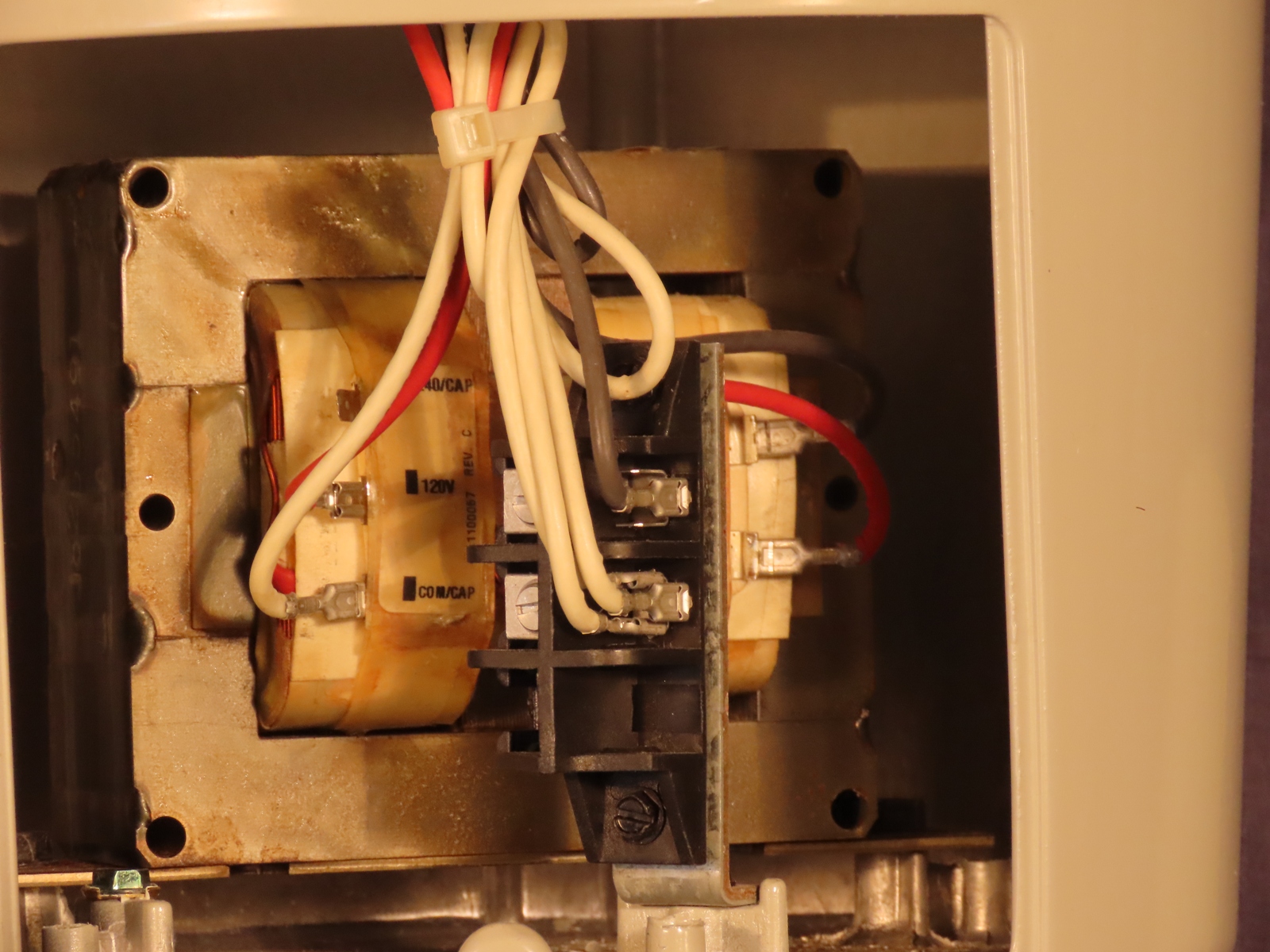
The live and neutral terminals are arranged vertically in front of the ballast, while the earth (Ground) termination is identified by a bolt with a green head that is attached to the casting.
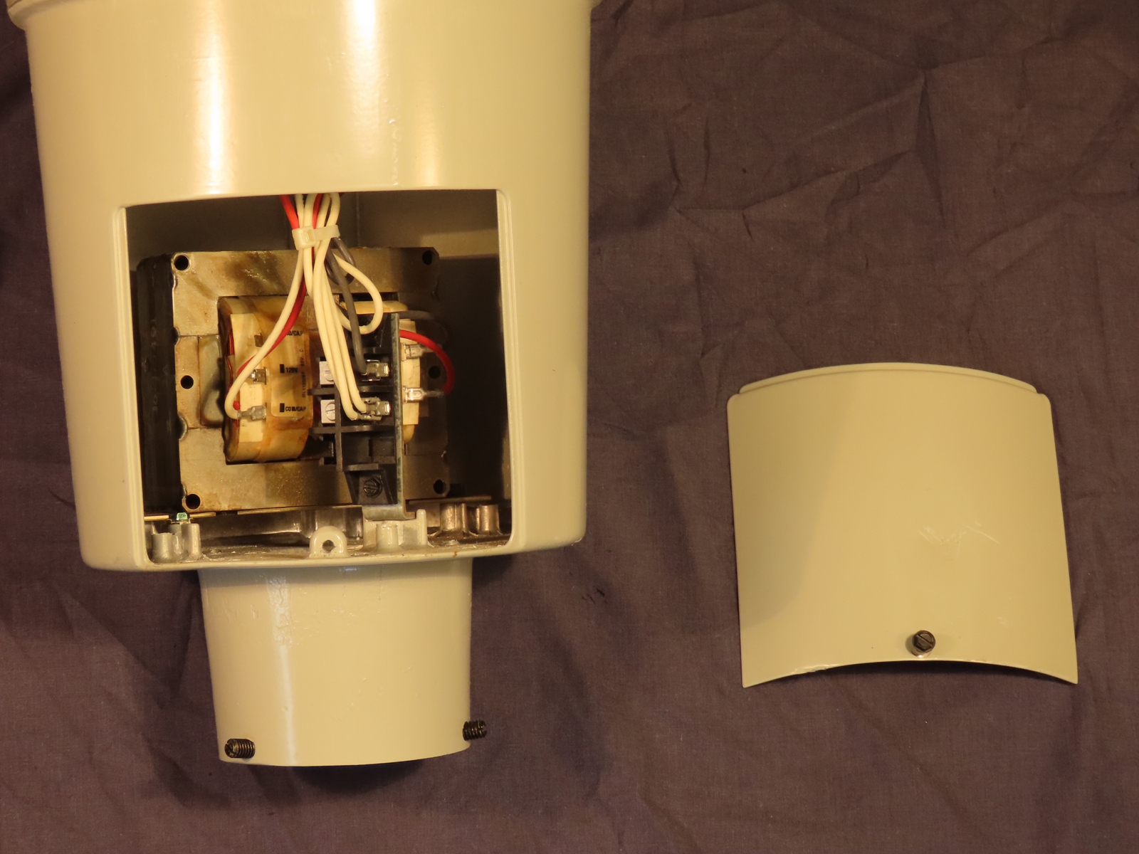
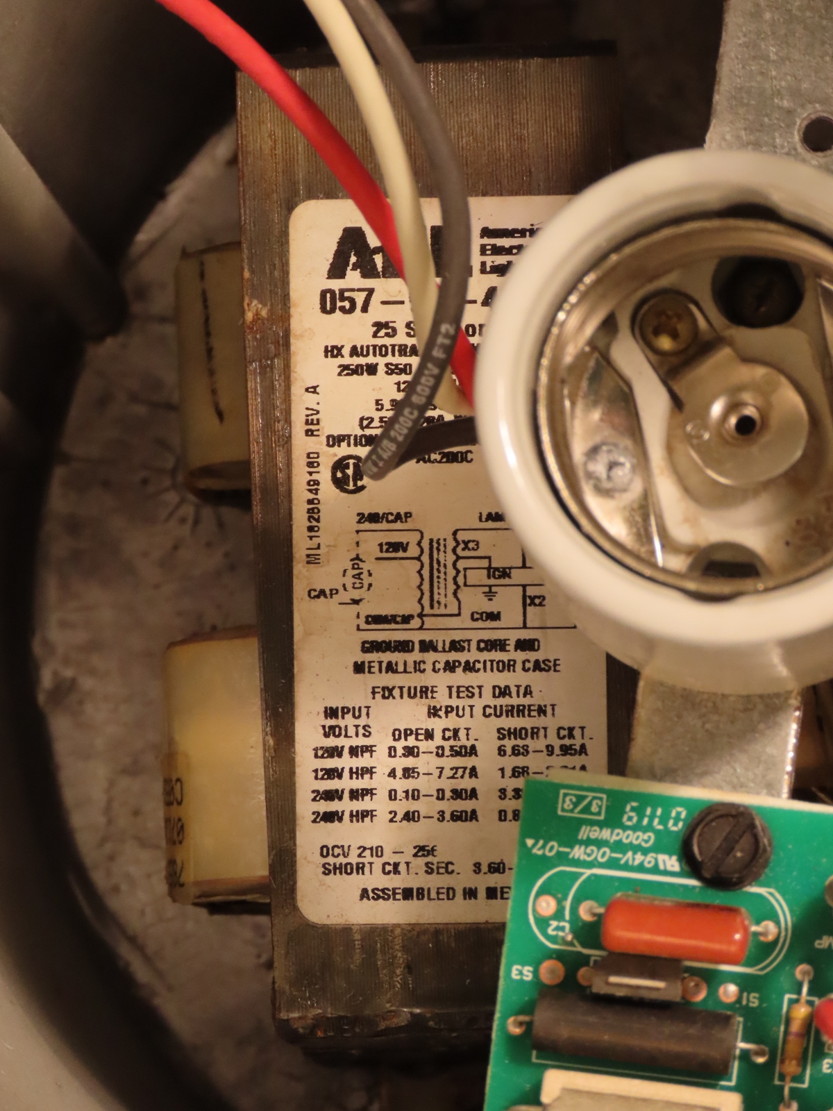
American ballasts, generally, have exposed coils and terminals, whereas most British ballasts have been of an enclosed design since the 1960s. Only my GEC Z9464 and Simplex Aries, have similar, open-coil ballasts. Notice that there is an unused 240 Volt tapping - originally, I had expected that the lantern would have a ballast designed for 120 Volt operation only, and was planning to rewire it using 240 Volt gear (and probably, of a lower wattage), but as there is an option to run it on the UK mains, I may as well give that a try instead!
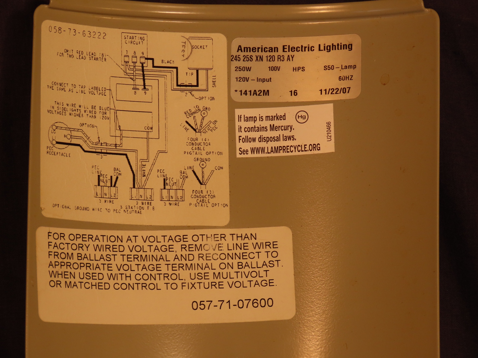
A wiring diagram for the whole lantern is provided on the reverse side of the panel, along with a label indicating that swapping the input voltage wire on the ballast is required in situations where the voltage is different to the expected 120 Volts...it's as if this lantern were made with me in mind! The part code 245 25S XN 120 R3 AY translates as:
245 - Contempo Post Top Series
25 - 250 Watt
S - HPS (SON)
XN - High Reactance / Lag, Normal Power Factor
120 - Voltage
R3 - Type III light distribution
AY - Acrylic bowl
This label also indicates that the lantern was made on the 22nd November 2007.
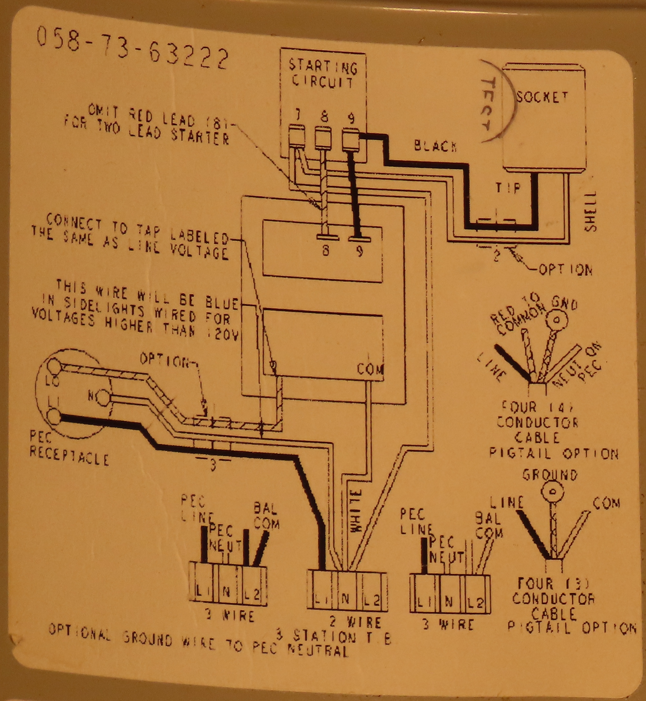
Close-up of the wiring diagram.
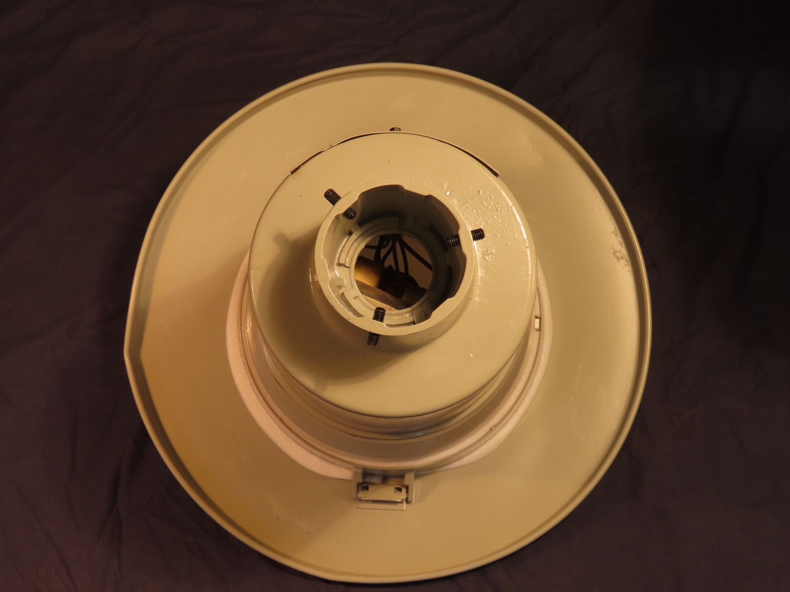
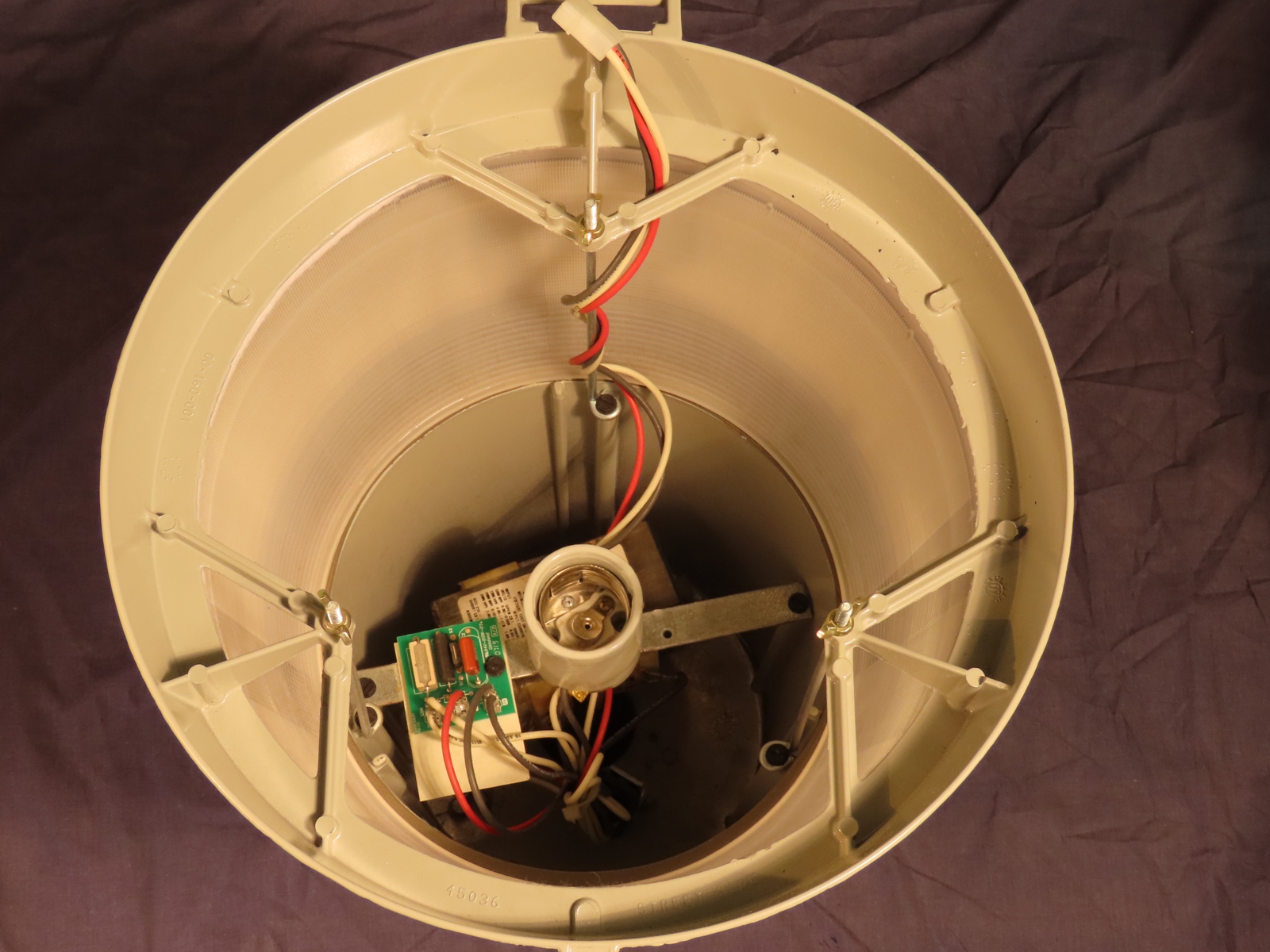
Inside the lantern, a central lampholder is visible. This is a 'Mogul' base; the American equivalent of a Goliath Edison Screw in Europe. It has a pitch thread of 39 mm, compared to the 40 mm thread of GES, though the difference is small enough that E40 lamps will fit into E39 lampholders (although the same is not always true the other way around).
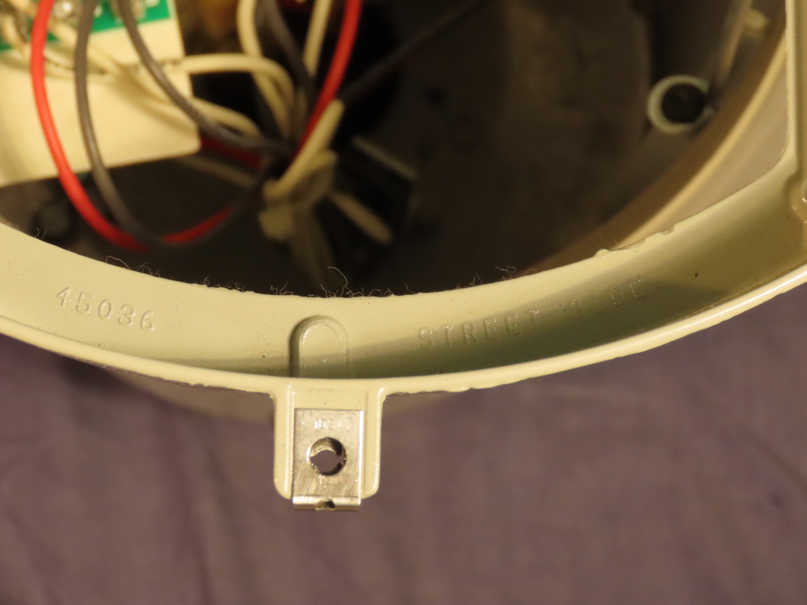
Cast into the top section of the lantern is 'Street Side'; ensuring that the lantern is aligned correctly, owing to the asymmetric refractor bowl employed.
This label is visible on the ballast; no capacitor is connected in the lantern.
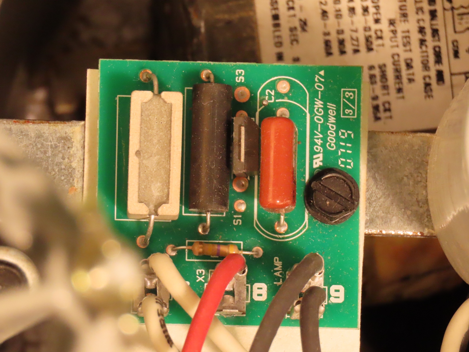
The ignitor (known here as the 'Starting Circuit') is an exposed circuit board; again, this differs from British and European lanterns, where the ignitor circuitry is contained within a plastic or metal case.
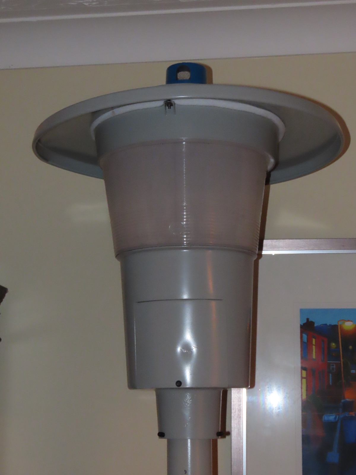
The Contempo was attached to a post-top stand fabricated by TAS Engineering of Burton-upon-Trent, which was then painted 'Telegrey 4' RAL 7047 (the closest match to the lantern's own paint colour) by R.L. Dumelow & Son, also of Burton, before being wired up.
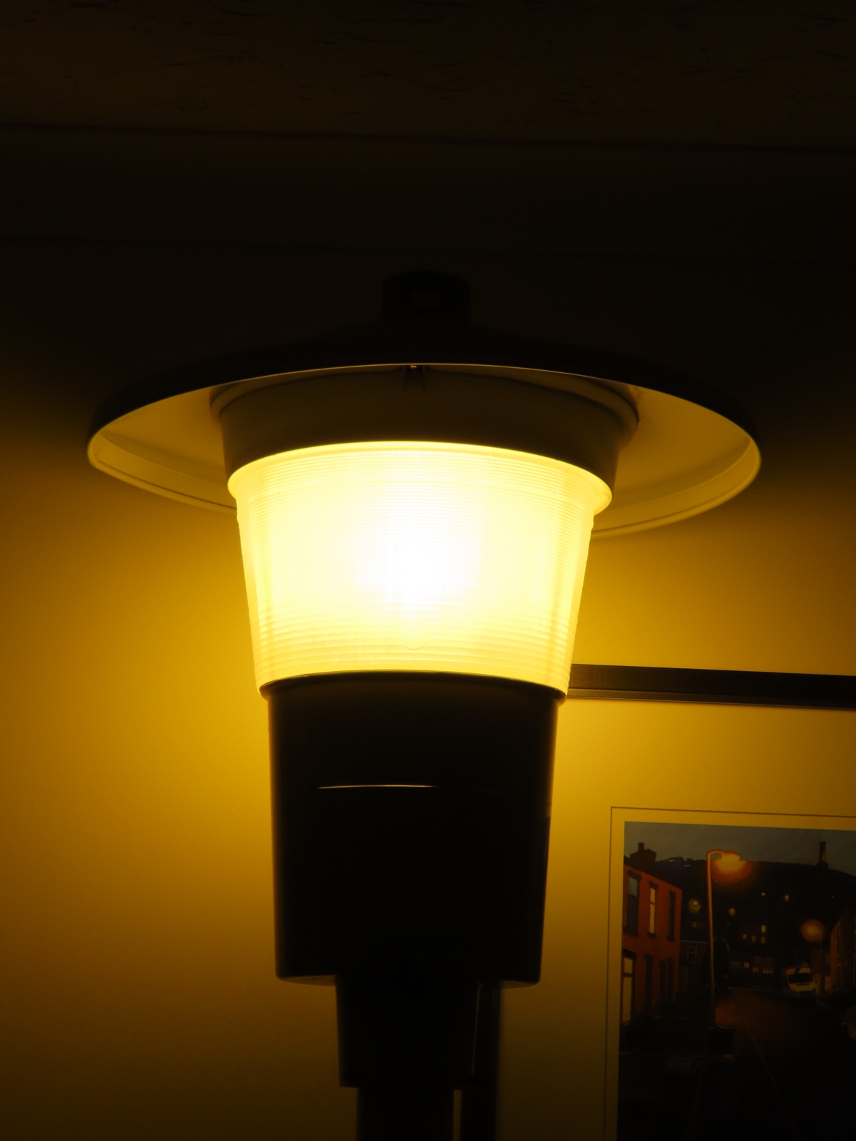
The lantern, pictured moments after being switched on.
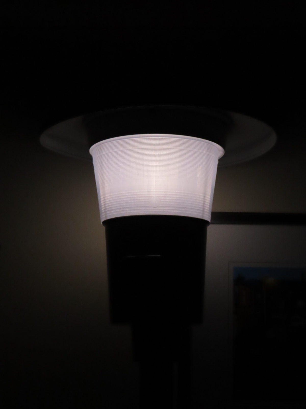
The refractor bowl helped to reduce glare with the lamp running at full brightness. Nevertheless, I couldn't help wondering whether a 250 Watt lamp installed post-top would make for a particularly efficient light distribution (although, the Thorn Gamma Three manages quite well). Notice that a small amount of light is able to escape through a narrow gap above the wiring access panel.
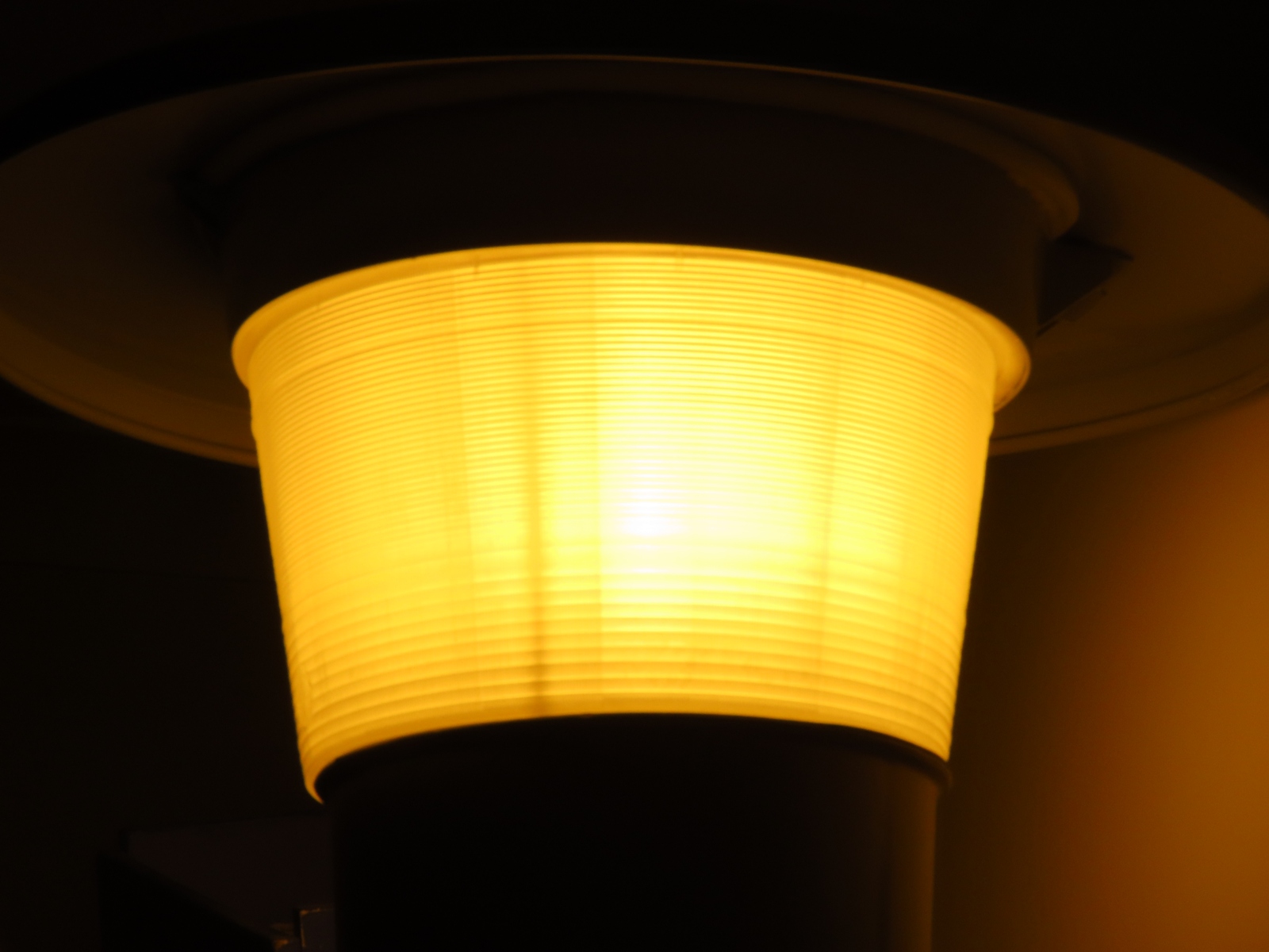
From the side, the beam is intensified slightly, as a way of providing lateral light distribution along the road.
Lantern operation video:
Testing with my energy monitoring device revealed the following results; the lack of a Power Factor correction capacitor in the circuit was evident. Indeed, initially, the current draw exceeded six amps but reduced to the figure shown below once the lamp had warmed up:
| Test Voltage (V) | Current being drawn at full power (A) | Measured wattage (W) | Apparent Power (VA) | Frequency (Hz) | Power Factor | True Power (W) | Difference to rated wattage | Percentage Difference |
| 236.2 | 3.79 | 381 | 895 | 49.9 | 0.42 | 375.98 | 125.98 | 50.39% |
With a 30 µF capacitor installed, the Power Factor improved slightly, and the Apparent Power figure decreased, although the True Power figure increased:
| Test Voltage (V) | Current being drawn at full power (A) | Measured wattage (W) | Apparent Power (VA) | Frequency (Hz) | Power Factor | True Power (W) | Difference to rated wattage | Percentage Difference |
| 239.2 | 2.27 | 399 | 543 | 49.9 | 0.73 | 396.38 | 146.38 | 58.55% |
CLICK HERE TO MAKE A MONETARY DONATION
© 2002 - English Street Lights Online