ELECO 'Goldenray Mk VIII' HW-747
Lantern acquired in January 2018.
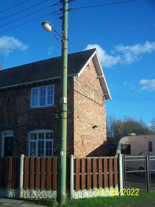
This lantern was removed from Station Road in Killamarsh, in the North-Eastern corner of Derbyshire, on the border with the City of Sheffield and County of South Yorkshire. The lantern, and its accompanying bracket, were decommissioned as part of a scheme to remove the street lighting equipment from the support poles carrying the overhead electricity conductors along the road, with the new lanterns being attached to lighting columns. Aside from a single example in Middleton-by-Wirksworth, I know of no other HW-747s in use on public roads in Derbyshire. My thanks go to the contractors at E-ON Highways Lighting for saving this lantern for me.
This picture shows the HW-747 as it appeared when installed. Ignore the date stamp; this is completely incorrect!
After removal, the remains of the lantern's AC Ford top-entry bracket, support bar and fuse box were still attached; however, the clamp used in attaching the bracket to the electricity pole was left in place; the bracket being cut away from this fixing point.
The lantern measures 17 1/4 inches (438.15 mm) in length, 11 3/8 inches (288.93 mm) in width and 9 5/8 inches (244.48 mm) in depth, including the threaded 3/4 inch BSP section, for attachment to the top-entry bracket. The bowl is formed from very thin acrylic, with refractor panels glued to the long, straight sides. Notice that the refractor panel is not positioned centrally, and the lantern is, in fact, installed facing the wrong way around on the bracket; in all likelihood, this error will have occurred during the lantern's attachment to the bracket.
The ELECO logo is even cast into what should be the 'front' of the lantern as a clue to how it should be positioned. The green paint used to protect the steel bracket has slopped onto the lantern's aluminium canopy during application, and I am surprised that the whole canopy was not painted, rather than just the bracket, even if it would only be appreciated by the person who acquired it for their Collection five decades later!
The underside of the bowl sports no refractors, though the plastic is diffused sufficiently to prevent a 'pool' of light forming beneath the lantern. Unlike the majority of side road low-pressure sodium lanterns, the bowl hinges to the side with the HW-747, rather than to the front or back.
Housed within the miniature fuse box is a porcelain fuse carrier (and re-wirable fuse) and a porcelain neutral block. Modern twin-and-earth/three-core-and-earth flat cable exits the box - this is likely to date from when a photocell control was added (the photocell was attached to the pole). Prior to this, the lantern may have been group-controlled using the 'fifth core' method, owing to its proximity to the overhead conductors - this being a common switching method in the Sheffield area. The grey photocell cable shows signs of fire damage - this was done by me after removal whilst trying to free the four screws holding the fuse box cover screws with a blowtorch. In the end, brute force won the day - a flat-bladed screwdriver was eased into the small gap between the cover and the box, and then forced further in using a claw hammer; the idea being that the wedge shape of the screwdriver would push the cover up slightly further, allowing the gap to be widened sufficiently for the claw hammer to fit, when the box lid was then prised open.
Opening the bowl reveals a very clean and tidy lantern interior, along with the lamp set deeply, owing to its integral control gear taking up much of the available space. The bowl fits into an aluminium support ring that tucks itself into the lip around the inside of the canopy when secured.
Removing the lamp reveals an imprint on the adjacent reflector / gear cover - the result of hundreds of thousands of hours of operation.
Removing the reflector allows the Philips L4045BX leak transformer and "Capacitors Ltd" 15 µF capacitor to be seen. Such is the age of the lantern that the lamp wattages stated on the transformer are 40 Watt and 60 Watt SOX; the forerunners of the 35 Watt and 55 Watt SOX wattages that were introduced in 1968 when tin-doped indium oxide film began to replace the less efficient stannic oxide outer coatings used previously. A clue for when the lantern last saw any major work done on it is the presence of solid green sleeving for identifying the earth conductors - this was changed to green/yellow in 1977. At this time, the lantern may have been rewired internally, with heat-resisting fibreglass-sheathed conductors replacing asbestos-sheathed conductors, though it is possible that the lantern never used asbestos conductors - different manufacturers stopped using this material at different times, once the hazards surrounding it became more widely-known. Certainly, the sealing gasket does not appear to be asbestos-based.
Whilst, unusually, the capacitor does not carry a manufacturing date code, the leak transformer does - it is a standard Philips type featuring a letter and a number - in this case, L3, or November 1963. The 22nd of that month would see U.S. President John F. Kennedy embark on (what would be) a fateful journey through Dallas, Texas, whilst in Britain on the same date, a little-known group, called The Beatles, would release their second album, With the Beatles. 1963 was also the year that a very different type of lamp to the one employed in this lantern - the fabulous Lava Lamp - was invented.
This view demonstrates the height of the ballast - there is not much clearance between it and the lampholder!
Cast into the inside of the canopy is: "ELECO LTD ST. ALBANS". This close-up view reveals, once again, the near-immaculate appearance of the lantern's interior.
Restoration on the lantern commenced at the end of May 2018, with the first task being to separate the lantern from the bracket. This involved stripping all components from the lantern before heating the top-entry connector with the blowtorch and then unscrewing the canopy from the coupler. In the process, some of the paint splatters were burnt, although as these are due to be removed anyway, this is not a problem.
The heating also left soot marks on the inside of the canopy, but again, as the canopy is to be restored, this is only a temporary inconvenience.
The canopy returned from being bead blasted on Friday, 6th July 2018. I decided to leave its exterior unpainted; hence, the slightly matte appearance of the cleaned aluminium.
As mentioned above, the internal white paint was renewed, however.
With new gaskets applied, the canopy was attached to a wall bracket later the same day, where its reassembly commenced. The bracket featured a 1′′ BSP right-angled bend fitted with a ¾′′ BSP reducer, and finally, a male-male coupler.
Without the bowl fitted, the tightly-packed nature of the control gear components becomes apparent.
The bowl and lamp were reinstated next.
The bowl clip still worked admirably, despite its ordeal!
Even with the control gear sandwiched into as tight a spot as 1960s' components would allow, the lantern still has considerable depth to it.
The slightly translucent appearance of the bowl complemented the initial blood-red output of the lamp to a tee.
The lamp warmed up within the space of a few minutes. It is seen here at almost full power.
An interesting observation made with the lamp at full power was that the edges of the gear tray could be seen in slight shadow at the front and rear of the lantern.
Lamp warm-up video:
Testing with my energy monitoring device revealed the following results:
| Test Voltage (V) | Current being drawn at full power (A) | Measured wattage (W) | Apparent Power (VA) | Frequency (Hz) | Power Factor | True Power (W) | Difference to rated wattage | Percentage Difference |
| 242.4 | 1.43 | 74 | 347 | 49.8 | 0.19 | 65.86 | 30.86 | 88.17% |
This test proved that the capacitor had failed - the Power Factor being one of the worst ever tested! A replacement 15 µF capacitor was connected (the old being left in the lantern) and this improved things slightly, but not immensely:
| Test Voltage (V) | Current being drawn at full power (A) | Measured wattage (W) | Apparent Power (VA) | Frequency (Hz) | Power Factor | True Power (W) | Difference to rated wattage | Percentage Difference |
| 245.7 | 0.51 | 67 | 125 | 49.8 | 0.53 | 66.41 | 31.41 | 89.75% |
Thorn Celest | Philips 'Delta' 2620
CLICK HERE TO MAKE A MONETARY DONATION
© 2002 - English Street Lights Online