Pearce Gowshall 'Warley' K30
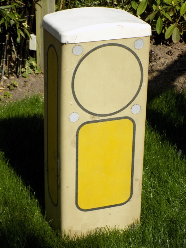
This version of the K30 bollard appears to be a slightly earlier design than my other example is, but is also designed to accommodate a vertical lighting spine within the bollard itself, rather than being base-lit with a ground-mounted up-lighter unit. This example was removed from service after being knocked (or blown) over, and not being able to be re-secured to its base.
This is a 'plain aspect' bollard; designed for highlighting the existence of a roadway feature (for example, exits on a roundabout) but not requiring motorists to obey any sort of specific traffic regulation when passing it. Another difference between this, and my other example, is that this bollard has had to endure being outdoors since the early 1990s; thus, the fibreglass body has faded and discoloured with age. As acquired, the bollard was covered in road grime and moss, but this was removed through pressure washing. The individual yellow aspect panels are smaller on this example.
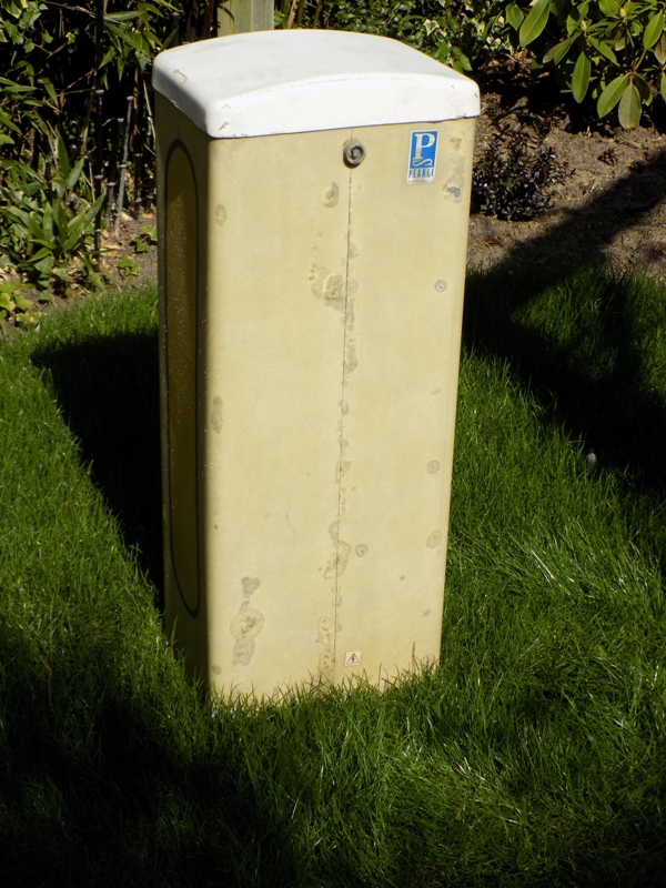
There is no access panel built into the back of this bollard; prior to acquiring it, I assumed that the tri-head bolt secured the top section, with all maintenance carried out from above. Numerous damp patches exist in the fibreglass, with a number (understandably) existing along the seam that joins the panelling together.
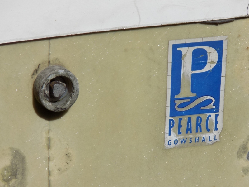
A close-up of the locking bolt, and a (somewhat) weathered Pearce Gowshall label.
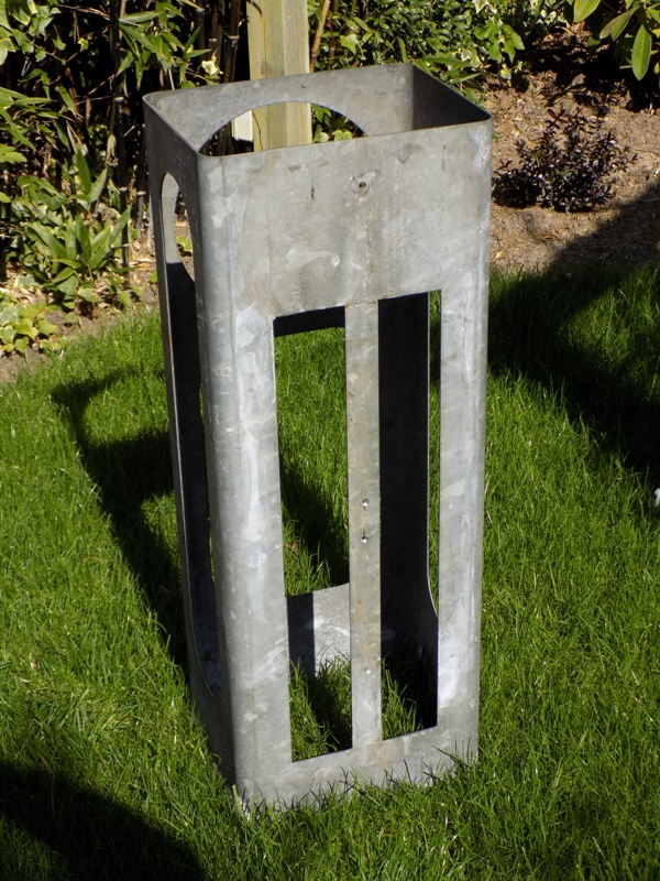
To my surprise, the top section of the bollard turned out not to be removable at all. Instead, the entire bollard lifts away from an internal steel skeleton, with holes cut through the portions that are meant to allow light to pass through. The vertical spine was long gone from within the bollard; it should have attached to the rear of the steel structure. When in use, the gear tray from a base-lit bollard had been placed at the bottom of the structure, and connected in place of the 'Reyrolle' socket that existed in the base section. Four bolts should have secured the above-ground metalwork to the ground box, but these had worked loose over time; eventually going missing.
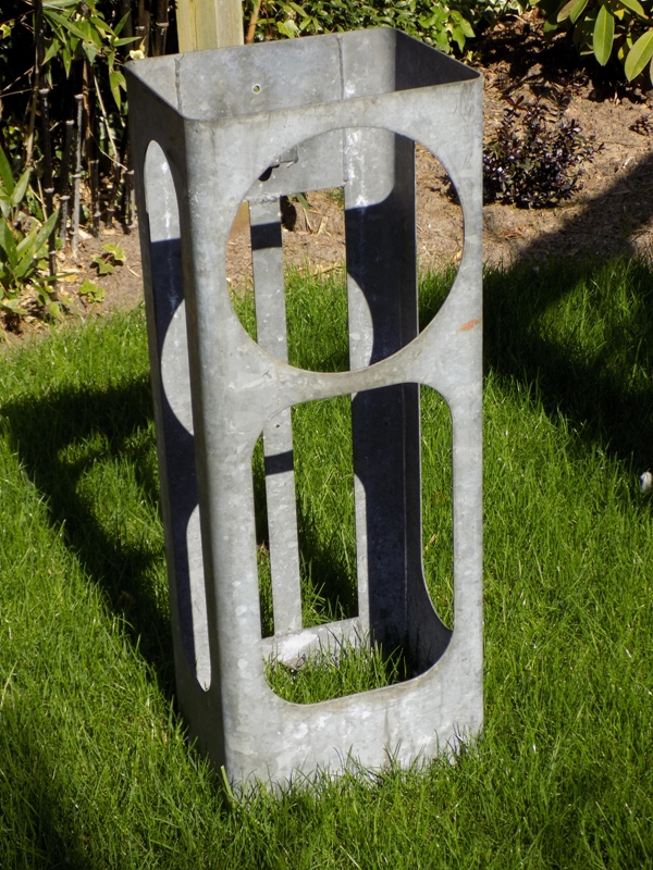
Two vertical slots are cut in the back of the metal support, in order to provide a small amount of illumination to the rear of the bollard - allowing it to be visible to traffic approaching it from behind. The two countersunk holes on the strut between these slots are not original - in fact, I drilled them as a means of supporting the replacement lighting unit.
Conveniently, there is just enough space between the two old lighting spine brackets for a 600 mm (2 ft) fluorescent light fitting to be accommodated. Thus, the Ring Slimline Fluorescent Fitting was attached and connected up.
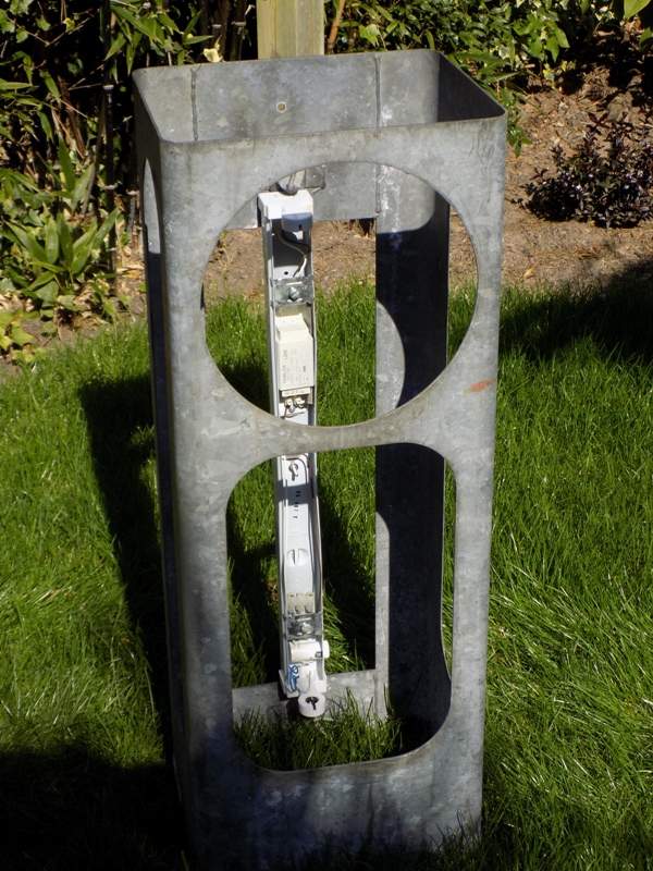
The now-operational fluorescent fitting, seen within the bollard's support frame.
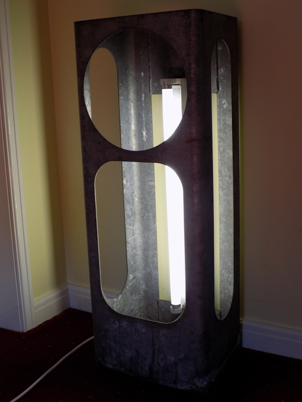
With the bollard skin back in place, the need for having the strategic holes cut in the frame becomes apparent. Notice, however, that the the holes do not line up exactly with the panels on the bollard, but are close enough that the bollard would be lit adequately at night.
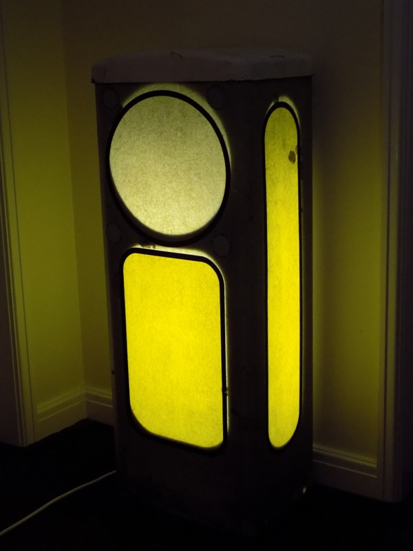
Although the above photographs show the bollard running the 18 Watt lamp that was included with the fluorescent fitting, this was only a temporary measure - the fluorescent lamp was substituted with a 10 Watt LED equivalent; testing with my energy monitoring device revealed these results after the change was made:
| Test Voltage (V) | Current being drawn at full power (A) | Measured wattage (W) | Apparent Power (VA) | Frequency (Hz) | Power Factor | True Power (W) | Difference to rated wattage (2 × 150 Watt) | Percentage Difference |
| 247 | 0.06 | 10 | 15 | 50 | 0.87 | 12.89 | 2.89 | 28.93% |
CLICK HERE TO MAKE A MONETARY DONATION
© 2002 - English Street Lights Online