Nissan Note Heater / Blower Resistor Card Replacement
If you find that your Note's blower fans are not working, even with the air conditioning indicator illuminated, chances are that there could be a fault with the so-called 'resistor card' that controls the blower operation. Alternatively, if the fan runs at full speed constantly, even when the selector switch is in the 'Off' position, the resistor card may be faulty too. I have created this page as a guide to accessing / replacing the card. Please be aware that this is for the 'E11' right-hand drive model of the Note (my example is a 2010 '60' plate) with air conditioning. The procedure may vary for other versions and markets; if you are in any doubt, please consult your logbook; local dealer, etc.
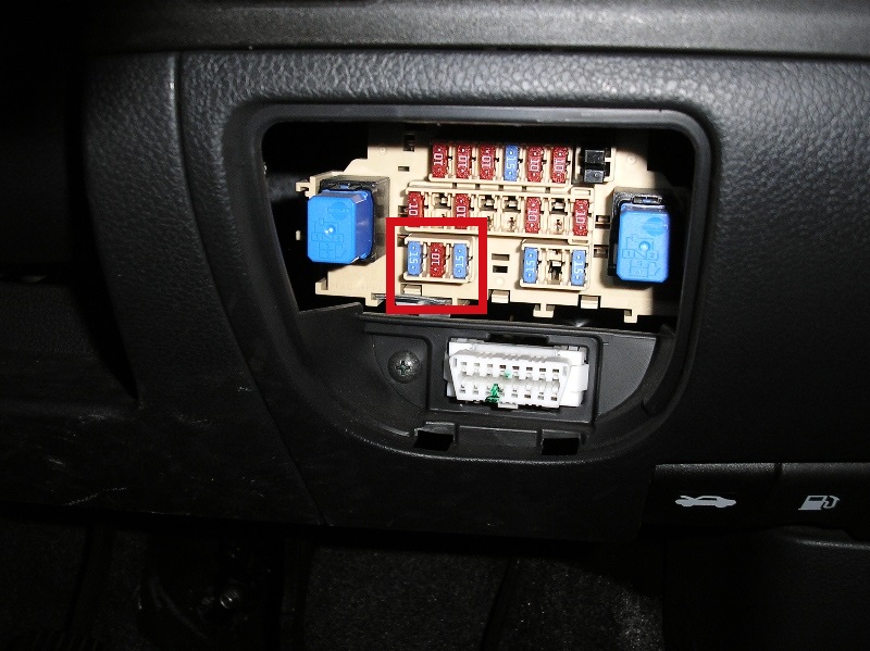
Firstly, check that the blower fuses have not failed. The fuses are located down and to the right of the steering wheel. Gently remove the plastic panel that covers them. The two blower fuses are located on the bottom-left; they are the two blue fuses rated at 15 A. The central red (10 A) fuse is for the air conditioning.
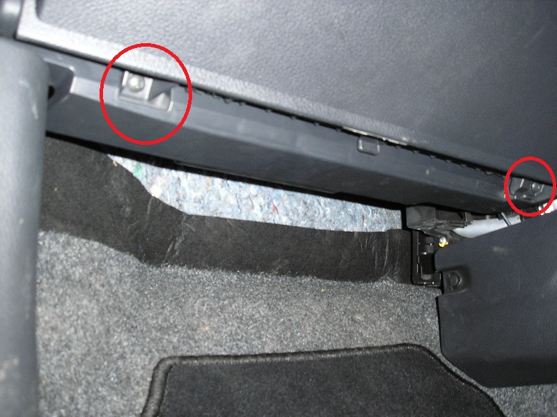
Assuming that the fuses all appear to be functional, you should now turn your attention to the resistor card. This is located behind the glove compartment; meaning that you will need to remove the compartment in order to access it. For this task, you will need a Philips-type ('cross') screwdriver (not the similar 'Pozidrive' screwdriver) - size PH2. I would advise that you use a short-handled screwdriver or else the glove compartment may impede access. Firstly, locate two screws at the bottom of the glove compartment, just above the passenger footwell, and remove them.
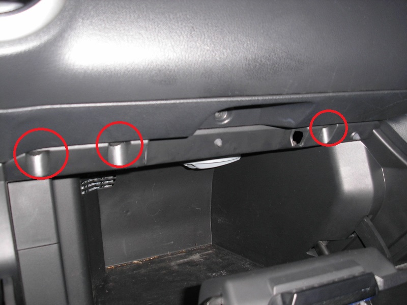
Next, open the glove compartment and remove three more screws that are located in the upper frame - there are two close together on the left and one on its own on the right. Ignore the central screw above the hand recess. The glove compartment can now be removed. Pull the compartment down and towards you - if you have a vent for keeping the compartment cool, a slight sharp tug may be required, in order to detach the vent from the duct above it.
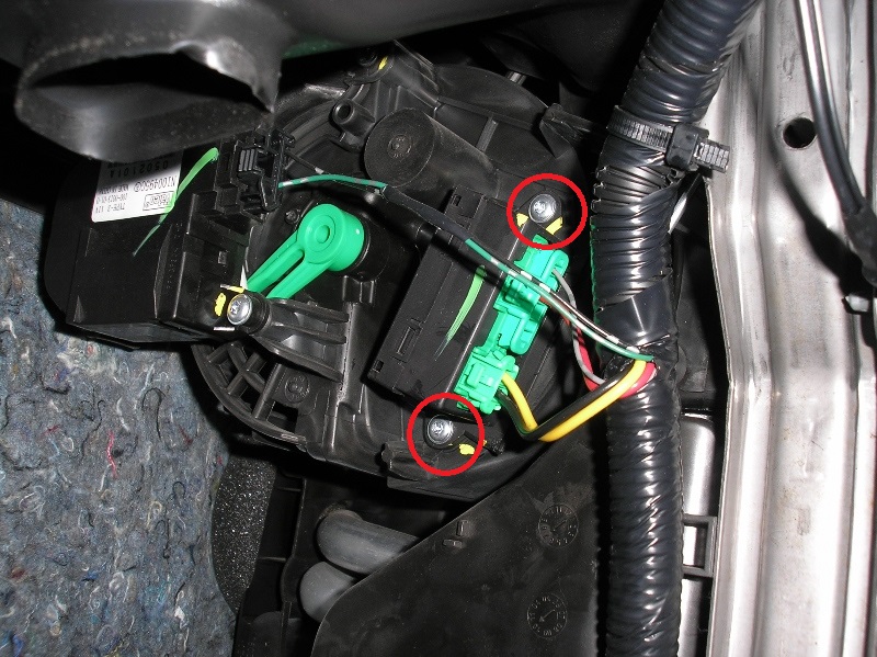
With the glove compartment removed, this should be the sight that greets you.
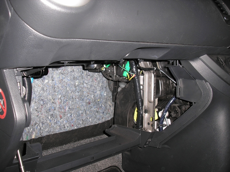
The resistor card is the object with two green electrical connectors attached to it. Remove the two 'Torx' bolts holding it in place (T20 size).
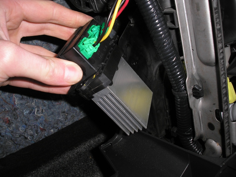
Grip the card using the black plastic section surrounding the connectors and gently pull it out of its housing. A lengthy aluminium heat sink is attached to the card - you may find that this prevents a smooth removal, but keep coaxing, and the card will eventually be free.
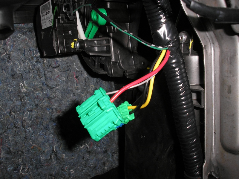
Ensure that there are no keys in the ignition before disconnecting the card. Use a small flat-blade screwdriver to press the locking catch of one connector inwards, then pull the connector away from the card (using the plastic, not the wires). Repeat this procedure for the second connector.
Examine both connectors, and the connection points on the card, for signs of failure. The old card is on the left in the picture below; notice that the second visible connector pin in the left-hand (larger) terminal is somewhat discoloured - a sure sign of overheating. The corresponding receptacle on the detachable connector was very slightly melted, but not seriously enough to require replacement itself. A new card is seen on the right.
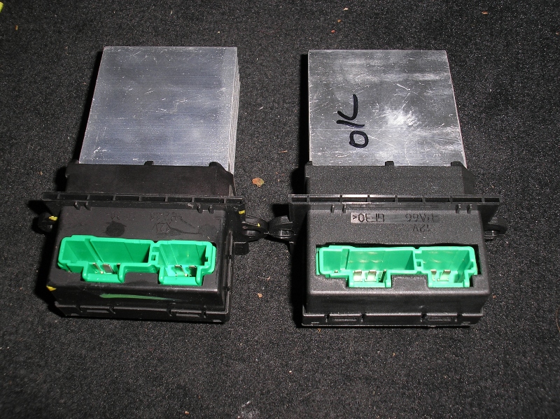
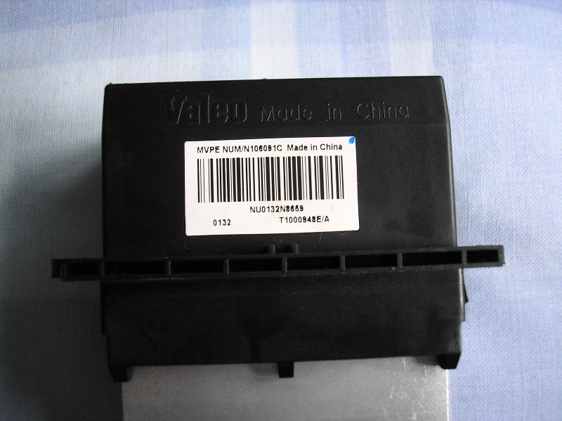
The old card carried a series of cryptic codes around a barcode - a search suggests that 'T1000948E' is the part code, although earlier versions of this product (made in France instead of China) carry the part code F657165/W, which seems to yield more UK-based search results (mostly for Renault, Peugeot and Citroen vehicles, though the component itself is the same).
Plug the two connectors into the card; a click confirms that the connectors are secure. Fit the new card into its slot and re-fit the two Torx screws.

Before re-fitting the glove compartment, you may wish to test to see whether the repair has been successful by powering up and running the blower - fortunately, in my case, replacing the card did the trick. When refitting the glove compartment, be sure to locate the vent and duct for the cooling system correctly - I found that a deft thump to the ceiling of glove compartment ensured that it was reattached. Replace the five screws (you may need to hold the surrounding part of the glove box inwards whilst doing this, in order that the screws correctly locate in their threads.

I hope that these instructions are of use - good luck with your repairs!
CLICK HERE TO MAKE A MONETARY DONATION
© 2002 - English Street Lights Online